
01
MINALOX 24 V DualWhite version Confirmed
| Product | MINALOX Art Framing Projector |
|---|---|
| LED technology | COB LED |
| Rated power | 10 WB |
| Luminous flux | 400 lm |
| Supply voltage | 24 V DC |
| Supply type | Constant Voltage (CV) |
| Colour temperature | 1800–4500 K DualWhite |
| Colour rendering | CRI > 90 |
| Adjustable optics | 20°–35° |
| Optical framing | Adjustable optical shutters |
| Warranty | 5 years |
Scope of this table
The values apply to the 24 V DC DualWhite version only. They do not describe 230 V or DALI versions, whose specifications are confirmed per project.
Not listed here
Parameters not listed in this table are not part of this specification. Request them for the specific project from MINALOX before they are used in a tender or calculation.
02
Four adjustments shape the light field.

Adjustable optics Confirmed
The beam is adjustable between 20° and 35°. Zoom until the light field slightly exceeds the artwork before framing.
Optical shutters Confirmed
Adjustable optical shutters allow the illuminated area to be shaped and aligned with the artwork. The achievable framing geometry depends on the optical system, installation position and adjustment range.
Focus
After framing, adjust the optical focus to achieve the appropriate edge definition for the artwork and installation.
Aiming
The luminaire is aimed at the artwork centre. The available adjustment depends on the mounting configuration selected for the project.
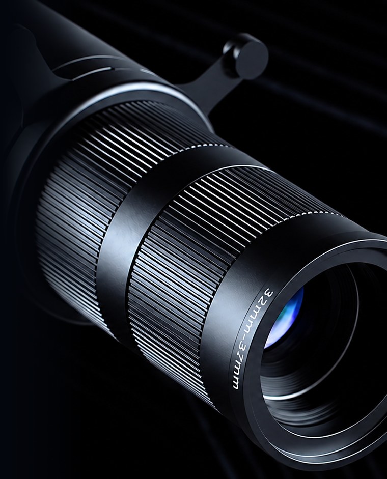
Lens marking “32mm–37mm”. This marking on the optical assembly may be visible in product images and in the product film. It is not the beam angle and not a specification value. The confirmed optical range is 20°–35°.
03
Selected according to the project.
The preferred MINALOX solution operates on 24 V DC, offering flexible integration into architectural lighting projects. Mounting configurations are selected according to project requirements.

| Configuration | Planning note | Status |
|---|---|---|
| Track | Flexible positioning along the track; suited to changing hangs. | Project-specific |
| Magnetic track | Minimal ceiling profile; luminaire position adjustable along the track. | Project-specific |
| Surface | Fixed position on the ceiling where no track is planned. | Project-specific |
| Recessed | Integrated into the ceiling for a quiet architectural appearance. | Project-specific |
Availability of each configuration and its interface to the chosen track or ceiling are confirmed per project. Compatibility with third-party track systems is not assumed. Keep every luminaire accessible: shutters and focus are adjusted by hand at the luminaire.
04
24 V DC constant voltage.
Supply Confirmed
The projector operates on 24 V DC from a constant-voltage (CV) supply. It integrates into MINALOX 24 V architectural lighting systems alongside other 24 V luminaires.
Planning the supply
- Use the rated power of 10 WB per luminaire as the planning basis for supply groups.
- Power supplies, cable cross-sections and voltage drop are dimensioned by the electrical designer for the specific project.
- Agree the position of power supplies and dimming equipment so they remain accessible for service.
DualWhite control
Colour temperature is set across 1800–4500 K and intensity adjusted through the project’s lighting control system.
Control options depend on the selected lighting control system.
The control sequence shown in the product film illustrates one possible integration. Control functions, interfaces and user applications are defined by the chosen control system, not by the luminaire.
Other versions Project-specific
230 V and DALI versions may be available for specific project requirements. Their specifications, mounting, dimming and control functions are confirmed per project and may differ from the 24 V version. The confirmed specifications in this guide do not apply to them.
05
Position follows from three values.
Ceiling or track height, artwork centre height and the aiming angle define where the luminaire goes. Enter the artwork size to see which beam angle the work needs.
Aiming & framing calculator
Illustrative- Setback from wall d
- 0.87 m
- Throw distance L
- 1.73 m
- Circular beam Ø 20° / 35°
- 0.61 / 1.09 m
- Required angular coverage
- 32°
- Available optical range
- 20°–35°
Preliminary geometric assessment: required coverage within the available optical range. Further optical verification required on site.
Preliminary geometric assessment based on an idealized circular beam. Actual framing capability depends on optical adjustment, installation geometry and the luminaire’s mechanical limits.
Simplified model: flat wall, luminaire aimed at the artwork centre from in front of the work, coverage of all four corners by a circular beam before framing. The artwork is kept at least 0.2 m below the ceiling.
Variables
| H | ceiling or track height above floor |
|---|---|
| h | height of the artwork centre |
| α | aiming angle from vertical |
| d | setback of the luminaire from the wall |
| L | throw distance to the artwork centre |
| θ | beam angle, 20°–35° |
Formulas
d = (H − h) × tan α
L = (H − h) ÷ cos α
D ≈ 2 × L × tan(θ ÷ 2)
required coverage θ ≈ 2 × atan(artwork diagonal ÷ 2L)
D is the circular beam diameter on a plane perpendicular to the beam axis, before framing.
About 30° from vertical is a commonly used starting point for wall-mounted artwork. Steeper aiming lengthens frame shadows and grazes surface texture; flatter aiming moves reflections towards the viewer.
06
Beam diameter by throw distance Illustrative
| Throw distance L | Diameter at 20° | Diameter at 35° |
|---|---|---|
| 1.0 m | 0.35 m | 0.63 m |
| 1.5 m | 0.53 m | 0.95 m |
| 2.0 m | 0.71 m | 1.26 m |
| 2.5 m | 0.88 m | 1.58 m |
| 3.0 m | 1.06 m | 1.89 m |
| 4.0 m | 1.41 m | 2.52 m |
D ≈ 2 × L × tan(θ ÷ 2). Circular field on a plane perpendicular to the beam axis, before optical framing.
Worked example Illustrative
| Artwork | 0.80 m wide × 0.60 m high (diagonal 1.00 m) |
|---|---|
| Artwork centre h | 1.50 m |
| Ceiling H | 3.00 m |
| Aiming angle α | 30° |
| Setback d | 0.87 m |
| Throw L | 1.73 m |
The round beam has to cover the whole work before framing, so the diagonal decides, not the width.
θ ≈ 2 × atan(0.50 ÷ 1.73) ≈ 32°
Zoom to about 32°, then use the optical shutters to align the illuminated area with the work. Under a 2.80 m ceiling the same work would need more than 35° at 30° aiming: increase the throw distance or review the layout with MINALOX.
If the required angle exceeds 35°, increase the throw distance or review the layout with MINALOX. If it is below 20°, the optical shutters reduce the illuminated area towards the artwork.
07
Setback by ceiling height Illustrative
Aiming angle 30° from vertical, artwork centre at 1.50 m.
| Ceiling H | Drop H − h | Setback d | Throw L | Ø 20° | Ø 35° |
|---|---|---|---|---|---|
| 2.50 m | 1.00 m | 0.58 m | 1.15 m | 0.41 m | 0.73 m |
| 2.70 m | 1.20 m | 0.69 m | 1.39 m | 0.49 m | 0.87 m |
| 2.80 m | 1.30 m | 0.75 m | 1.50 m | 0.53 m | 0.95 m |
| 3.00 m | 1.50 m | 0.87 m | 1.73 m | 0.61 m | 1.09 m |
| 3.20 m | 1.70 m | 0.98 m | 1.96 m | 0.69 m | 1.24 m |
| 3.50 m | 2.00 m | 1.15 m | 2.31 m | 0.81 m | 1.46 m |
Effect of the aiming angle Illustrative
Ceiling 2.80 m, artwork centre 1.50 m.
| Angle α | Setback d | Throw L |
|---|---|---|
| 25° | 0.61 m | 1.43 m |
| 30° | 0.75 m | 1.50 m |
| 35° | 0.91 m | 1.59 m |
Field on the wall Illustrative
Aimed obliquely, the beam meets the wall as an elongated field. Example: H 2.80 m, h 1.50 m, α 30°, θ 20°.
| Width at centre | 0.53 m |
|---|---|
| Upper edge | 1.91 m above floor |
| Lower edge | 0.74 m above floor |
At 35° the lower edge reaches the floor and the upper edge lies at about 2.11 m. The optical shutters reduce the illuminated area towards the artwork.
Values are geometric estimates rounded to 0.01 m. They support early planning and are confirmed on site during commissioning.
08
Plan the light with the hang.
Position early
Fix track or mounting positions while the room is being designed, from the intended artwork positions and centre heights.
Aim from in front
Aim from in front of the work wherever possible. A lateral offset adds keystone distortion that then has to be compensated with the optical shutters, within their adjustment range.
One projector, one work
Framing works best when each projector is dedicated to one artwork. Plan one luminaire per framed work.
Field and frame
Zoom until the field slightly exceeds the work, align the illuminated area with the optical shutters, then adjust the optical focus.
Colour temperature
DualWhite 1800–4500 K lets the light follow the palette of the work and the mood of the room. Choose per work, not by rule.
Intensity
Set the level relative to the room and evenly across the work. A modest level reads bright when the surroundings are calm.
Colour rendering
CRI > 90 supports a faithful rendering of pigments, varnish and skin tones.
Artwork sensitivity
For sensitive works, plan illuminance, exposure and conservation requirements per project with the responsible conservator.
09
Keep the light on the work, not in the eye.
Reflections
Protective glazing, varnish and glossy prints reflect light like a mirror: the reflection leaves the surface at the same angle as the light arrives. Light from above is therefore mirrored downwards; for works hung around eye level, the reflection passes below the viewer’s eyes.
Flatter aiming moves the reflection towards the viewer. Check from normal viewing positions and adjust angle or position where reflections appear; anti-reflective glazing can help for critical works.
Glare control
- Position and aim so the lens stays out of view from normal viewing positions and seating areas.
- Check sightlines from entrances, corridors and staircases, where viewers see the ceiling at a flatter angle.
- Use the optical shutters to reduce light on adjacent surfaces, door openings and furniture.
- Review frame shadows on deep frames: steeper aiming lengthens the shadow at the top edge.
Optical framing reduces unwanted light on the wall around the work. Some spill and reflected light remain and depend on the room, surfaces and settings.
10
Set each projector under final conditions.
Commission after the artwork is hung and the room’s other lighting is in its final state.
- Position the luminaire.At the planned setback, in front of the work.
- Aim towards the artwork.Point the beam axis at the centre of the work.
- Adjust the optical beam.Zoom within 20°–35° until the field slightly exceeds the work.
- Shape the illuminated area.Align the illuminated area with the work using the optical shutters.
- Adjust the optical focus to achieve the appropriate edge definition for the artwork and installation.
- Verify the result from normal viewing positions.Check spill, reflections, frame shadows and glare.
- Adjust intensity where supported.Set level and colour temperature in the control system.
Before handover
0 / 4A tick list for site use; nothing is saved.
A practical workflow that complements the installation instructions supplied with the product. Electrical installation is carried out by a qualified electrician.
11
What we need for your project.
- Number of works, with width and height of each.
- Artwork centre heights and hanging positions.
- Ceiling or track heights and room plans or sections.
- Preferred mounting configuration and ceiling construction.
- Lighting control system planned for the project.
- Glazing, varnish or other surface details of the works.
MINALOX proposes the lighting layout and lists the details to confirm. Mounting interfaces, other supply versions and control integration are confirmed per project.
Five-year MINALOX warranty
The MINALOX Art Framing Projector is covered by a five-year MINALOX warranty.